


On Friday Umit finished his board in the morning and during testing had issues with his motor control. We ended up helping him troubleshoot and found that a wire was in the wrong place. It took about a hour to get it right after which he passed and we all helped him strip his board and we finished at about 2pm. I had finished my board by lunch time but we decided to test on Monday. I did as much testing as I could before livening it up.
The tests with the power off are:
- Visual.
- Make sure there are double nuts on the main earth and neutral.
- All the cables are secure.
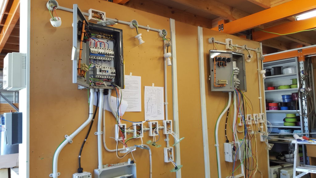
- The earth tag in the DB needs to be near the top for ease of identification.
- Cables should be cable tied and fixed to the side of the panel.
- Cables going to the front panel should have an extra degree of protection. ie another insulation sleeve because the opening and closing of the door over time could damage the cables.
- Main Earth (MEM link disconnected)
- The resistance has to be 0.5 Ohms or less.
- Insulation resistance test (MEM link disconnected)
- shoot 500v DC between all conductors. 5 in a 3 phase system.
- If there are components at the end of the circuit, these need to be removed or phase and neutral shorted together and test between active and earth.
- PEC (MEM link disconnected)
- The next step is to test the resistances (and hence connectivity) of the Protective Earth Conductors. These are the earth wires to power sockets and light sockets. The resistance needs to be 1 Ohm or less.
- Polarity Test (MEM link CONNECTED)
- A remote earth is required. The installation is livened and a multimeter used to ensure that the active conductors are 230v and the metal case is 0v. If there is a transposition, the metal case will show 230v. Without a remote earth, 230v would be measured but a transposition not detected because how could you detect neutral was phase and phase was neutral?
- Test between active and earth/neutral. You should get 230v. Between phases (for multi phase installation) you should get 400v. Between earth and neutral you should get 0v due to the MEN link.
- You should also test the polarity at each of the power sockets. This is important to ensure that active (ie red or brown) is connected to the right pin.
- By fact of testing polarity, you are also testing continuity.
- Earth Loop Fault Current (MEM link CONNECTED)
- Here an ELFC meter is used. This meter simulates a fault and firstly tells you the resistance of the EFL. Table 8.1 needs to be used to determine what the impedance needs to be below based on the breaker in place. Eg a C10 breaker needs to have a resistance of less than 3.07 Ohms. Typically the meter will read 0.67 Ohms or something in that range.
- After the impedance is determined, the meter will then determine the PSCC. The Prospective Short Circuit Current. This current will be 230v/0.67 Ohms which is 343 Amps. This means that if a short circuit was to occur, 343 A would flow through the circuit causing the breaker to trip much faster than the 0.4 seconds required. (Due to the non linear curve).
- Note that the MCB (Minature Circuit Breaker) is designed to protect the circuit and the appliance connected to the circuit. It is not designed to protect people.
- Residual Current Device Test (MEM link CONNECTED)
- RCD’s in NZ are rated at 30mA and must trip within 300mS. A test is done to simulate a fault at 0.5x, 1x and 5x the rated current. at 15mA, the RCD must not trip. If it does, throw it away. At 1x, the RCD must trip at 30mS or less. At 5x, the tripping time must be 40mS or less.